RoboxDual › Forums › Technical Support › [Resolved] Filament laying down and then stopping & starting
This topic contains 34 replies, has 4 voices, and was last updated by Mike 6 days, 15 hours ago.
-
AuthorPosts
-
June 4, 2017 at 1:09 pm #40027
Hi
I’m at a loss to understand what is happening with my Robox Dual. It has been working fine after a logic board and Bowden cable swap, but since it decided to eject a filament, it has been playing up.
I have cleaned nozzles, run purges, and done everything that Automaker has asked, despite it say I have removed the head when the fan was still working which I didn’t. In one of these processes, the Bowden cable unbeknown to me was elongating at the left hand connection closest to the extruder path, and had gone a stringy white, as it was thinning, which resulted in it snapping off the gland internally, and the first thing I knew about it, was the filament was spooling inside the case.
It was the feed to filament 2 that was playing up, but fortunately I had a spare Bowden tube to get me going. I recalibrated the head nozzles and the alignment test print values added, and I printed a test 2mm thick 31mm square plate, and it was fine.
Now a few days later, filament 2 is doing its stop start cycle again, where the head starts, and then after a while material is laying down, then it fades, then it starts up again. There is no slipping or clicking from the extruder feed motor, and I have rotated & switched the thermo bed, but it still does it in the same place. It even does it on the purge cycle, nothing for the first 20-25mm or so, so I have to keep aborting the prints. The same thing happens with same filament in filament 1, and it isn’t making sense.
Anybody got any bright ideas please, because it’s totally unusable at the moment.
Mike
PS The only other unusual thing that is happening is the printhead is oscillating left to right and bashing the left hand side internal casing for the last few print attempts, but only on start up, shortly after you hit Make in Automaker.
-
This topic was modified 6 days, 4 hours ago by
 Pete. Reason: resolved - gith hand Z drive nut stripped
Attachments:
You must be logged in to view attached files.June 4, 2017 at 3:59 pm #40029Hi again,
Early days, but after re-calibrating the nozzle opening, and nozzle height I seem to be on track again. The nozzle height issue is apparent when you look at the picture as the filament lay down is too wide, but as I use this occasionally I hadn’t spotted it.
I also noticed that checking that the paper is just clear of the nozzle is a bit hard to detect, as most paper will slide easily anyway, so what I did see was that the head was being tensioned by the paper thickness, so I just increased the gap, until the head didn’t appear to drop down minutely anymore. Everything seems OK so far …
Mike
RE the PS, I have gone into “Advanced” mode just to look at the Diagnostics flags for X Limit, and the switch is working on the side of the head, but it doesn’t appear to trigger against the LHS of the casing where there is a detent detail in the plastic. Not sure why this is, as nothing has been taken to bits. 😕
- This reply was modified 1 week, 2 days ago by Mike.
Attachments:
You must be logged in to view attached files.June 4, 2017 at 4:37 pm #40032Hi yet again,
After successfully printing out these 31mm test squares, I tried the model I need to print out for a friend, and it’s the same issue in the original post. Bed fully degreased with alcohol in-between prints… so frustrating.
It looks like the Z limit has changed again, as the filament lay down is being marked by the nozzle, and I’ve checked the bed material isn’t warping by pressing down with tweezers. 😕
Mike
Attachments:
You must be logged in to view attached files.June 4, 2017 at 4:59 pm #40034Hi again!
OK, the X limit stop doesn’t appear to hit any corresponding part of the Robox, anybody have a picture of this area, as I’ve just looked on Google images, and there doesn’t appear to be anything to hit in these either. 😕
Thanks
Mike
June 4, 2017 at 6:38 pm #40035@17bt The stop/start on the filament may be due to a very low nozzle height. What are the values in the nozzle calibration chart under Head EEPROM?
The X axis issue is caused by the metal frame that the cable chain is attached to hitting the side of the Robox. Check that the screw on the right side of the X-Carriage is not fully tightened. If this screw is fully tightened, it will cause both of these issues as the metal bracket needs to allow the X-carriage to move freely. If the screw is fully tight, loosen it by at least one full rotation and test again. If that does not resolve the Z issue, loosen it another full turn. You should be able to see a gap between the screw head and the metal bracket. That should solve the Z issue if the calibration is correct, though the nozzle height may need to be calibrated again. You are looking for a nozzle height between 0.20 and 0.40 for most DM heads.
If the X axis issue persists, bend the metal frame that the cable chain attaches to to the right a bit and it should stop. If that doesn’t solve it, there are some more drastic steps I can provide.
I operate two Betas and four Production Robox.
I am the US/Canada Technical Support engineer for the Robox.
See my 3D Hub site at https://www.3dhubs.com/phoenix/hubs/benJune 4, 2017 at 8:48 pm #40036Hi Ben,
Thanks for the heads up on the X limit “rattle”, it was indeed the back of the printer carriage support catching the blue left hand side. All fixed now thank you.
The Z head values were 0.40 & 0.11 when I posted last, but I have changed it to 0.45 and 0.15, then 0.20 using my test squares , and this has visibly improved the finish.
I am printing in TechABS using the default Robox settings for Normal print quality, and I have noticed the prints are curling off the bed, so I will add a brim to stop this, and peel it off afterwards. I do think my PEI sheet is bowing in the middle with heat, which is surprising me, because I didn’t expect it. I have turned it around so it is glossy side up, and applied the heat cycle to it, to see if it improves, but it doesn’t seem much better. I will do some more tests tomorrow, but thanks for you input, as this afternoon that pesky Robox was making me regress into Tourettes syndrome. 😉
As another observation, the purge cycle was not displaying as it should, which is probably the head being too close, and maybe a bowed PEI sheet.
Attachments:
You must be logged in to view attached files.June 4, 2017 at 9:17 pm #40038@17bt There is an article in the support portal about “bounce” in your print bed. Your bed should always be matte side up for ABS and should always be cleaned with isopropyl alcohol before every print. If you find that after removing the bounce from the print bed and cleaning the bed your adhesion does not improve, you can lightly sand the matte side with 300-400 grit sandpaper or a green Scotchbrite pad to roughen the surface a little.
I operate two Betas and four Production Robox.
I am the US/Canada Technical Support engineer for the Robox.
See my 3D Hub site at https://www.3dhubs.com/phoenix/hubs/benJune 4, 2017 at 9:25 pm #40039Cheers Ben, I’ll check “bounce’ out. in the support portal.
I have some Scotchbrite pads, and P320-400 aluminium oxide paper, but to be honest I never use the glossy side, and I was thinking of wet blasting it with the Vixen aquablaster at the CNC workshop. That way I could just reverse the sheet to reverse the “bounce” or heat distortion when the problem surfaces again.
Mike
June 5, 2017 at 5:40 am #40040Hi again,
This early morning I did some test squares in filament 1 & filament 2, and tweaked my calibration settings for Z to 0.55 & 0.30 get a reliable first layer, plus offset the models to the left to avoid the problem area on the PEI sheet. They surface finish is a lot better, so I tried the troublesome model, and it was the same as before.
Using a narrow beam LED torch and looking at the nozzle head from side on, I could see what was happening very clearly, and the areas where the filament wasn’t laying down are down to the PEI sheet bowing upwards, and then stopping the filament from coming out of the nozzle, and that explains why it tapers off to nothing at one point, and splurges out at the next point on the path when the clearance opens up.
When cool I shall try sanding and reversing the PEI sheet, as I can see it lifting at the perimeter location tabs, and springing when I press down with the tweezer handles. Worst case I will have to buy a PEI sheet, but is this a known issue with materials other than PLA, a reaction to using solvents on the one surface repeatedly or just degradation with time?
Mike
June 5, 2017 at 9:44 am #40046@17bt Well done with the testing and reporting, it is all nice and clear.
Try physically bending the PEI into the shape you want. It is very flexible and can be done cold. Heat wont help much as it would need to be 320°C + before it will change state.
If the shape cannot be resolved create a support ticket as it may be possible to replace it under warranty. Take it out and take photos of it on a flat surface, eg a kitchen worktop.
The bowden tubes can stretch or buckle reasonably easily which can change the internal diameter and make it harder for the filament to move. It might be worth getting some spares if yours have discoloured or have flaws.
The first layers you show do look too close to the bed surface.
In the pic below I allowed the left side to print as normal but pressed down slightly on the top of the head for the right object.
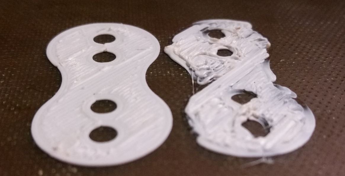
It isnt an accurate representation of a nozzle too close as the pressure I applied varied but the result is excess material in some areas and missing material in others. The pressure of excess material can build up to a point where the nozzle is pushed up when it releases or in extreme cases the extruder will start to skip as it cannot push any more material forward. If this repeats a lot or for long periods then the bowden tube or other sensitive parts may be damaged.
During the Nozzle Height Calibration you are looking for the point where there is very little pressure against the bed surface from the nozzle but it is still touching. This is the point where there is no strain on any parts.
The Z height detection will press the nozzle against the print surface until the electrical Z height contact is broken. This point in the stepper rotation is recorded but there is some strain on parts, when you provide the calibration point the firmware will use the difference between that and the detected number to set the “home” position for Z accurately. For a first layer this is mixed with data from the 9 point probe which occurs before each print and adds some variation to the first layer height by allowing both Z motors to move up and down. First layers always default to 0.3mm to allow free movement of material, the point will be 0.3mm above the calibrated height and following the terrain map provided by the self levelling probe.
June 5, 2017 at 1:47 pm #40054Wow, Pete, thanks for a comprehensive reply & useful explanations how things work.
I had already checked the PEI sheet on a granite bed at the CNC workshop, and yes it’s domed, and you could rock it like a turtle on it’s back, plus if you pressed down on the clip points on one side it would lift at the other. I didn’t take any pictures, but I did hand sanding to the gloss side with P320 paper to abrade the surface.
When I got home, I checked it out and it seemed OK, but unfortunately, the reworked glossy side suffered from the same bed to nozzle clearance variation, and it can be seen in the image below, IN fact it did the same when reversed to the original surface, and that was. surprise, as I expected the sheet to behave like a Belleville washer or spring.
When I look at it more closely, it is definitely curled upwards in the corners, despite trying to bend it in an arc in both directions when cold etc.
Another interesting point, is when I apply pressure to the bed, in the areas where I think the sheet is high (as no filament has been laid previously), I still get the nozzle “scraping the surface and restricting the flow, because no amount of pressure downwards will lower the bed further. If I insert a 0.4mm thick 20mm wide palette knife, I can replicate a similar height variation within the PEI sheet, that restricts the flow of filament, so I’d guess it’s about 0.3mm higher at this point. Have checked the heater bed for flatness, and it seems OK without using a proper straight edge, and there is no lumps on it to deflect the PEI sheet.
I can get some CMM measurements off the granite bed if you like, or I can post it down for you guy to look at, but I can definitely say it is crowned no matter what, as I shot a cross hair laser across it, and I can see the beam changing when I depress the sheet with the palette knife. If I look at the nine point or 3X3 self levelling points prior to printing, I can see my high point is halfway between the middle ones, and the right hand middle point. It’s virtually smack in the middle of the right hand side clips too.
I am beginning to wonder if the clip points are allowing the material to flex with time, as the RH corners are definitely slightly “gull winged” and when I press these, you can see the high point flexing looking at a paused & cancelled print remnant. If I had some small clips I would clamp the sheet in this area to see if it behaves better, but by pressing down on the bed with the palette knife doesn’t make things completely go away. That can only mean the material is blown slightly on there is some sort of gantry error towards the right hand side. I suppose I could bias the print to the right and see if it gets worse?
I’ll probably have to raise a support ticket, as I cannot use this printer as is, and I will order some more Bowden cables.
Thanks again
Mike
Attachments:
You must be logged in to view attached files.June 5, 2017 at 1:53 pm #40058 -
This topic was modified 6 days, 4 hours ago by
-
AuthorPosts

You must be logged in to reply to this topic.


