RoboxDual › Forums › Technical Support › [Resolved] Filament laying down and then stopping & starting
This topic contains 34 replies, has 4 voices, and was last updated by Mike 1 week, 5 days ago.
-
AuthorPosts
-
June 5, 2017 at 2:26 pm #40060
If you print on the left side of the bed is it better?
If the unit is new and you can show the PEI is not flat then there shouldnt be any problem sending you a new one. Perhaps you can also check that the aluminium heat spreader under the bed is also flat, you would need a straight edge which can fit in the diagonals of the bed.
I’ve had the same printer on my desk for about 3 years now, it gets a lot of abuse. The current print surface is probably about a year old because I print Nylon a lot and ruin them all the time (Nylon and TPU stick so well they rip the fibres out). It has “bounce” all over it but it is pretty even across the surface, it works fine though. I think my clips have been tightened too far but because it prints ok I wont change it.
I am surprised that your print surface can have such a large effect and that it is not being tuned out by the bed mapping. It is possible that it is the “edge” of a larger sheet as these are produced in sheets so it may have flaws. Or that the lump is between probe location so is not being detected.
You might like to inspect the Z home spring which is on the rear of the head, it should compress and return in a regular way without binding at either end. It should allow the head to rock backward without much resistance beyond the weight of the head. If this spring is not operating as designed then it will effect bed levelling and lots of other calibration.
June 5, 2017 at 4:21 pm #40061Hi Pete,
I did raise a support ticket, and warranty is not being offered. This aspect of owning this printer is slightly galling, it’s always my fault, when clearly the PEI sheet is visibly distorted almost blistered or domed, and all I’ve done is print a few things with it using the default material settings for Robox tested materials Now with hindsight and observing the PEI sheet behaviour, and not being disrespectful, I’m not sure as a product designer the clips or the clamping system is a good design in the first place.
Genuinely thanks for your input, but I’m not sure where I’m going with this now, as £24.90 + shipping probably isn’t going to solve the issue, because it doesn’t explain why the print fails predominately on the right hand side even if you push the PEI sheet downwards. I will measure its thickness with a Faro arm tomorrow, and report back, but my enthusiasm has been dulled.
Mike
June 5, 2017 at 5:58 pm #40062@17bt Just bend the PEI sheet to remove the curve. If the clips are too tight and it pulls the PEI sheet back to an upward curve, bend the clips up until it doesn’t. I assume there is no warranty coverage because there isn’t actually anything wrong with the sheet or the bed and if you will please follow the instructions provided you can fix it pretty quickly. Or because you have physically damaged the sheet. I print nylon and TPU and have yet to damage a PEI sheet after three years. I use a razor blade paint scraper to lift prints if they are strongly adhered.
As a fellow product designer this is really a pretty good system based on what it needs to do. I have looked at alternate designs and they have just as many drawbacks as this one and are much more complex.
I operate two Betas and four Production Robox.
I am the US/Canada Technical Support engineer for the Robox.
See my 3D Hub site at https://www.3dhubs.com/phoenix/hubs/benJune 5, 2017 at 6:01 pm #40063@17bt Have you tried raising or lowering the aluminium heat bed via the torx screws dotted around the edges? I’ve found that doing so has helped to even out the levelling for the PEI bed, which has to be placed convex side down.
For what its worth, I’ve found that the bed mapping doesn’t really seem to work for me, it has always printed too close to the bed on the reel-less side of the Robox (although I’ve been told that this is because of the Bowden tube pushing on the head).
June 5, 2017 at 9:38 pm #40065Hi again guys and sorry Pete, my response was before I saw your second one.
@Ben, I know how to bend the PEI sheet, and I have done this. a few times before, did so previously today, and quite adept at it, but it will not correct the “distortion” in the right side of the bed. I haven’t done anything untoward with this printer, if I had I would stick my hand up. I also don’t have the same experience or use levels as some of you, but as I don’t usually have a problem printing, something is clearly amiss.
I have after conversing on the forum, got a better idea of what a print should look like, and I am pleased with where they were, unfortunately these last few days and the other faults have spoilt my prior experiences, and it is extremely frustrating. I was pleased with the forum responses, as they seemed to pointing me in the right direction, but I am also jaded by support language that infers “it’s always my fault” when clearly all I am doing is using the printer when it allows me, and I don’t deviate from Robox default values in Automaker. Later you find some of these “faults” are to be expected for one reason or another. 🙂
I also like you find a lot to admire in design of the Robox, and I have even recommended it to others who would struggle with a Prusa i3, and compared to an Ultimate 3 someone I know has, it’s king of a machine compared to that.
@pete, the unit is not new, and it was recently upgraded by the “shop”. I did slacken and reseat the head after the machine had cooled down, and the head does tip back at high level as expected, as far as I can tell, but no matter what I do the RH side of middle is not printing out properly.
@uhuglue, I have not slackened the bed Torx screws, as I didn’t know you could, or would need to. The machine is on a level table surface, so there is no twist in the chassis, and it’s hasn’t been moved from this position over the last few months. Thanks for the tip being convex side down.
I am managing a print at the moment by biasing it to the left of the bed, but that has an odd first layer flaw on the left now too. “the spot of Jupiter” 🙂
Thank you for your responses.
Mike
Attachments:
You must be logged in to view attached files.June 6, 2017 at 2:44 am #40069@17bt Based on your pictures, it is painfully obvious that either your print head is too low or your printer is not mapping the bed correctly. Since you have the cable chain installed, the Bowden tube influence should be minimal and would cause the first layer to be thicker, not thinner. Since the problem persists all the way to the edge, it points to the nozzle height being off.
What are the Z values for the head calibration?
I operate two Betas and four Production Robox.
I am the US/Canada Technical Support engineer for the Robox.
See my 3D Hub site at https://www.3dhubs.com/phoenix/hubs/benJune 6, 2017 at 2:46 am #40070@uhuglue I would be very careful about loosening or tightening the bed torx screws. They are meant to retain the heat spreader and heating element. If you loosen them you may cause a poor contact situation between the head spreader and the bed thermistor, allowing the bed to get much hotter than it should. If the bed exceeds a certain level, it will blow the thermal fuse and require repair.
I operate two Betas and four Production Robox.
I am the US/Canada Technical Support engineer for the Robox.
See my 3D Hub site at https://www.3dhubs.com/phoenix/hubs/benJune 6, 2017 at 5:42 am #40071@bhudson, it’s only painfully obvious in places and there is no consistency except, the right hand side of the print is too close to the nozzle. The left hand side “spot of Jupiter” is right underneath a mapping point, and this was only seen in the last print, because I offset the model to the left.
The Z values have been changed to try (from 0.55 & 0.30 to 0.5 & 0.4) and resolve the situation, and as I am using the same Robox TechABS but different colours in the DM head, I have switched between the two to see if I get any variation in performance.
I do not but the head is consistently too close on the right hand side of the bed, and when I shine a LED light at low level, I can see the nozzle pushing filament like a toothpaste tube onto the bed, and obviously not where the bed is getting too close to the nozzle. Obviously increase the Z height too much and there is no adhesion, and the filament stays tubular, and subsequent layers delaminate easily.**
I agree the Z mapping does appear to be a possible issue, based on what responses I have seen from others with tired PEI sheets still printing satisfactorily, but I have checked the head moves back, and after this LH print has finished, I will remove the head again (it stalled because this Robox reel had a crossed filament spool and the filament was not feeding correctly*), and double check everything looks OK.
A question for anybody, are the Z values saved in Automaker for the head updated live, as in if you alter them whilst a model is printing, does it use these values real time or the next time a “Z mapping ” event takes place?
Anyway the print has finished, and other than the “z height too low” patch on the first layer it is OK for what is needed, unfortunately I now need to do a bigger print next time, and this will push the head into the right hand side of the bed, where the z height “issue” is.
Mike
*BTW, this is the second time I have seen this from a Robox sourced reel 😕
** I am using Filament 2 for the LH model, and it is delaminating with finger nail pressure, so I will need to drop the z height calibration slightly.
Attachments:
You must be logged in to view attached files.June 6, 2017 at 8:00 am #40074Hi again,
Another update, something is definitely amiss with the Z mapping or Z height, as my models are now skewed, so they have varying thicknesses. I look at a previous print, and a 3mm model was close on 3.6mm high printed in the middle of the bed, whereas the latest on the LHside are over 4mm. I understand, messing with the Z height might distort this, but I have just looked at the red holder I made for the PC+ filament, and that is within a few hundredths of a mm across itself.
The latest larger circular print varies from 6.25mm at a LH mapped point to 5.15 at the middle mapped point. I cannot see 1mm bounce in the PEI sheet, in fact it’s pretty negligible in these areas.
Any ideas please…this is definitely a Z height issue.
June 6, 2017 at 8:17 am #40075You won’t believe this, but I might have found the issue, hopefully one of you technical guys can tell me whether this is correct.
I have just shone a torch at the Z carriage, and I noticed the bottom nut looked greasy, and then it moved, BUT it is threaded, so whats happening. It looks like it is a bottom nut & the upper nut has come undone, because I cannot understand how the Z carriage for the head is located if these are loose, in fact I know it isn’t. 🙂
That’s exactly what the problem was, and I’m sorry my PEI sheet obsession was making me look in the wrong place, these nuts that lock the carriage to the Z feed screw, are loose. This machine was shipped back to have the carriage and DM head fitted, so I think I can understand why I have had this issue now, and it isn’t obvious until you see it.
The carriage has a hexagonal extruded detail to keep these captive, and a spring to give a bit of play, preload the nuts etc, so how do you fix this please? Do you lower the carriage so the plain portion has the lower nut in it, then wind back with the upper nut within the carriage hexagonal profile?
Mike
- This reply was modified 1 week, 6 days ago by Mike.
Attachments:
You must be logged in to view attached files.June 6, 2017 at 8:47 am #40082So the reason why the nozzle was so close to the bed on the right, and got worse further right you went, was there was no support from the Z screw on this side, and the head was cantilevering from the LH support. Altering the Z height in calibration mode to suit the print was a sticking plaster.
It is always the simple things, and I’ve learnt another thing about the Robox, because I took the side cover and did a test print on the left and the right, and just propped up the Z height carriage with my finger to give it a preload, and the filament extruded and laid down fine, in fact too much “nozzle” height make the filament come out like toothpaste, and wriggles it way onto the bed. 🙂
Mike
Attachments:
You must be logged in to view attached files.June 6, 2017 at 8:50 am #40084We would never intend to imply fault without due cause, perhaps the wording of some of our solutions or experience from the support team has caused them to seem this way and is something we should look at. Typically the automated systems of Robox do a very good job of setting things up so they work, sometimes these can be tuned better with human interaction. Sometimes that interaction is worse than the automated system or a flaw somewhere in the system is misdiagnosed. The worst offending customers are usually the most experienced -“rep rap experts” - because rep rap demands so much tinkering these experienced users can make Robox worse very quickly, mainly due to the vast differences between Robox and other machines. Although Robox is not perfect, the “faults” are more often down to the way users -even the experienced users- have (mis)understood the calibration wizards or meddled with the systems.
Back to your issues: Recalibrate the nozzle height, at the start of this there is a part where the difference between the 2 nozzles heights is checked, this probes with each nozzle several times and compares the results, if the results of each probe vary then the probing continues for longer swapping nozzles and probing. When a result is always varied outside of a certain tolerance the the calibration can fail. If the variation is close to tolerance then the test will go for longer if there is a problem. A normal test of nozzle height difference will finish within 5 probes of each nozzle and continue to the next stage where you will be asked for input. Be sure to remove the print surface for this test as described in the wizard.
If the print surface is flat and the head spring is operating then you an try the following:
Test the Z limit contact, the top rail should be clean and free of grease or debris. The contact which touches the top rail should also be clean and free of debris as there is an electrical circuit which runs through the rail to the contact. This contact will wear over time but it is unlikely that this is the problem. You can watch the operation of this and other limit switches in the diagnostics window.
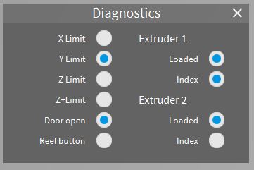
Ignore Z+Limit, look at Z Limit and tilt the head backward, the indicator should light up. Move the head to each side and test again, you can push it around while power is on, it will just need to home again later. It should reliably light whenever the head is tilted enough to break the contact between the top rail and the tab you can see behind the head.
Next check that the Z drive components are in good order. There is a stepper motor on each side to drive the gantry up or down. The smooth vertical rails simply run ballraced linear bearings, one on each side, the threaded rod which is turned by the stepper motor has an assembly of 2 nuts and a spring which reduces backlash when this drives up or down. Because of the spring you should be able to push the gantry upward by around 5mm on each side, it should spring back down again but move freely in this way. If you push downward the gantry should not move on the threaded bar beyond some flex in the assembly, don’t push too hard as the moving joint between the smooth and threaded bars is a plastic cylinder and can be damaged.You can see the right side but to see the left side you would need to remove the cover, observe the safety warnings in the following link before opening any panels. https://robox.freshdesk.com/support/solutions/articles/1000132454-open-the-case-to-access-the-electronics-danger-
In the Maintenance section of Preferences is a Z test button. Clear the bed and build area of any obstructions before running this, it goes all the way to the top of Z travel then back down again so if there are any obstructions the head can become trapped. There is not result from this test beyond what you observe, watch the smooth and threaded rods in particular for any catching or indications that they cannot run freely, there may be debris in the threads which will need to be cleaned and then new lubrication applied. A small amount of grease for the threads, machine oil for the smooth rail (never oil the top horizontal rail).
-
AuthorPosts

You must be logged in to reply to this topic.


