“Big Dave and his little brother make parts in days that would otherwise take weeks or even months to prototype or manufacture conventionally. With cost savings of over £40k achieved in the last year alone, our Robox 3D printers have become an integral part of our business and we’re pleased to call CEL our partners.”
BIL Group Ltd
After getting off to a rapid start my Dieselpunk inspired crawler ground to a standstill while I waited for parts, now that they have arrived everything is up and running. Sometimes when the design and printing go well they are the quickest part of the project!
All of the parts fit in the RoboxDual, you can find them here for download. I printed the vast majority of the project in ABS, but PETG will do just as well.
Since sculpting is not my strong suite I called in the assistance of my talented friend Fotis Mint who was kind enough to model a cool head for the driver. There is nothing quite like 3D printing and the internet to make a collaboration across thousands of miles seem like you are working in the same studio.

The torso and all of the joints were modeled in Fusion360 after which I sent the torso and neck piece to Fotis Mint who sculpted on those in ZBrush.
From the perspective of design for printing however the most interesting part of the project are probably the various arm joints on the driver figure. I needed a lot of freedom of movement, so that the steering wheel servo could make the arms move, without putting much strain on it. I also wanted to avoid fiddly assembly and printing with supports, so I came up with a three piece design that results in 5 axes of movement. Two of the joints are simple pivots using 1.75mm filament off-cuts as hings, but the others print in place, as shown below. These are the sorts of things that would be impossible to do with other manufacturing methods.
The assembly of these joints can be seen at the 7 minute mark of the video below.
- The hand joint is supported during printing by an hourglass shape which then breaks and allows free movement. There is significant clearance in the wrist joint to provide rotation as well as an angular movement.
- Printed in place this is a simple rotating joint. Note the chamfer on the bottom of the inner ring, to ensure that the base layers do not fuse.
- The upper arm is printed in the orientation shown, once printing is complete the red circled joint is easily broken by twisting, freeing the joint to rotate smoothly.
One of the best things about 3D printing is that it lets me work fast enough that I can get an impulse project from concept to reality before I lose the inspiration.
I have had the idea to build a small tracked RC vehicle for ages, but when I came across the Tiny Trak it just wouldn’t get out of my head.
Usually when an idea gets stuck in my head I am forced to scribble it in my notebook to make it go away, but this time that didn’t work and the sketch quickly turned into a CAD model and two weeks later was a printed design sitting on my desk.
This little beastie is 200mm long, powered by two continuous rotation servos, and will have an FPV camera in place of the driver’s head, allowing us to pilot it from the driver’s seat. I’ve designed it to be easy to print and assemble and its small size and low price should make for a fun weekend project.
- The beginnings of a plan…
- Fusion 360 CAD model
- Printed in TitanX Grey ABS on the RoboxDual, the whole design prints without supports.
- TitanX ABS painted directly with hobby acrylic paints
The project is now waiting on some electronics, and a design for the driver, stay tuned for updates, and files once they are tested!
This is a short one, but a good one!
See the video for full assembly instructions, as well as my first powered test, and find the files for download here if you’d like to try it out.
In the last post we got a working differential together, since then I have been designing the axle tubes, axle shafts and the drive shaft.
Axle Tubes
I have mentioned from the beginning that I am trying to keep the complex mechanical components compatible in size with off-the-shelf RC components, so I have made the width of the axle and the mounting points exactly the same as the Boom Racing SCX10 axle that I used on my rat rod build.

Printable rear axle with differential compared to Boom Racing SCX10 axle for size
The housing of the differential has been redesigned so that all of the tolerances are contained within one part, and the cover simply screws down on top, holding the two largest bearings in place. Nothing has an overhang more than 45 degrees, so it is all printable without support.
- The differential housing and cover shown in their print orientations.
- New housing holds whole assembly in place far better than the previous clamshell.
Inside the axle tubes there are two bearings which support the printable axles shafts. The axles shafts have provision for an M4 rod down the middle, which provides both strength and the opportunity to use standard RC wheels if desired.
- Section shows the internal structure, especially the M4 rod which transmits torque to the wheels as well as allowing them to be attached
- One tube removed, exposing the axle shaft, drive cup, bearings, and 12mm hex
- Complete assembled differential, axle tubes and cover are held on with M3x8 screw
Printed Prototypes
I printed and assembled prototypes based on this design and it went together well. My plans to test immediately were delayed due to some mistakes I made in the sizing of my driveshaft, but the assembly feels satisfactory when turned by hand, I have high hopes for the first test!

The assembly, printed in ABS filament
Next Step
Stay tuned for the assembly and test video of the rest of the axle shortly, as well as work on the drive shaft and universal joints.
Over the past few weeks, with a brief hiatus due to international travel for my day job (I’m an Electrical Engineer in the telecoms industry), I have been plugging away at the design of the rear differential.
I have a few design goals for the rear axle
- Approximately the same size as a “standard” 1:10 crawler axle (both to make this re-usable in other applications and to make it possible to use a commercial axle on this build)
- Functional open differential
- Accept standard RC wheels with a 12mm hex drive
- Rugged enough gears to handle, at least, a “silver can” 540 motor
- Look fairly realistic (not too important in this build since it will probably be hidden)
- Preferably printable without support
Of course the rear axle can be made significantly smaller (or stronger, in the same envelope) if we go from a open differential to a spool, which will be a suitable modification if it is to be used on a rock crawler.
Design Approach
I first attempted to design from the outside inwards, starting with my goal diameter for the differential and designing gears to fit inside it. This turned out to be a bad idea, causing endless redesign, it was much more sensible to design the gears and build the casing around it.
There are other aspects to keep in mind, almost all of them relating to tolerances. For example, if a bearing recess is part of the face that contacts the printer bed then the slight bulging can prevent the bearings from fitting.
Designing Bevel Gears
Unfortunately Fusion360 doesn’t have a decent tool to create parametric bevel gears and designing them properly yourself is no mean feat. This is a real nuisance because we have to import gears from elsewhere and then design around them.
Fortunately there is a very nice script written for OnShape which you can find here and it is not too much trouble to set them up as you like, export as STEP files and import into Fusion360.
In order to keep my design “semi parametric” I positioned all of the gears sensibly with respect to the origin, and then defined variables which correspond to the gears dimensions. So long as all of the dimensions of the housing correspond to these variables and aren’t referenced to the gear objects themselves it is fairly easy to swap the gears out with others.
This iteration of the design provides another approximately 2:1 reduction, which means that we should be able to shrink the transmission that was designed in the last post.
- Differential Mk III sectioned
- Differential Mk III closed
- Differential Mk III exposed gears
Rapid Prototyping - Use It!
This is more of a personal lesson, but perhaps it is worth reminding. If you are like me then you design something to 85% and then realize that you could have designed it better, then you repeat the process, without ever printing anything. With something that takes 100’s of hours to print that may make sense, but for tiny parts like this it is just foolishness. There is a lot to be learned by just printing the item, and trying it out as is.
These are pictures of the first functional assemblies, hastily printed in ABS (not printed on a Robox, I look forward to seeing how well it handles the small pieces though!).
- Mk I - Test Print
- Testing the mesh of the sun and planetary gears. The screw used as an axle will be replaced with a smooth shaft.
- Test assembly shows that the design works, but there is too much play in the side gears.
- Here the M3 screws which hold the assembly together are visible, but it is also clear they will interfere with the bearing.
- Complete functional assembly, despite a few tolerance issues it works perfectly
- Print orientation should always be considered in the design phase.
Video: Assembly and Test
Some things are best expressed in video, and assembly is one of those things, so here we go!
One day we will be able to 3D print functioning combustion engines in 1:10 scale, but for now the car will have to be driven by regular old electric motor, it’s sad but true, I know!
Why Reduction Is Needed
Small electric motors spin incredibly fast, but don’t generate much torque. In order to make them useful we need to gear them down appropriately.
Most RC cars get the majority of the reduction done in the first step, using a very small pinion on the motor, and a very large spur gear, but this is not really suitable for a realistically shaped gearbox, so I will use multiple stages of gears to achieve the desired reduction.
Design Goals
I have the following design goals for this reduction box.
- Motor must be low (for centre of gravity)
- Fully printable (without support wherever possible)
- Strong gears, big teeth, easy to print
- All gears to be hidden in a (semi) realistic enclosure
- Minimize unique parts
Selecting a Ratio
Although you can get a lot of power out of the “540” sized motors commonly used in RC cars, they still need a lot of gearing down, so it’s time to design a reduction gearbox.
I have done some rough “back of the napkin” calculations which show that a final drive ratio of about 8.5 will be decent starting point. The glory of printing is that we can experiment and revise once the car is working
| Theoretical Max Speed Calculation | |||
| Example 1 | Example 2 | Example 3 | |
| Motor RPM | 17000.00 | 22000.00 | 22000.00 |
| Brushless Motor kV equivalent (2S) | 2297 | 2973 | 2973 |
| Brushless Motor kV equivalent (3S) | 1532 | 1982 | 1982 |
| Final Drive Ratio | 8.50 | 11.00 | 8.50 |
| Rear Wheel Diameter (mm) | 95.00 | 95.00 | 105.00 |
| Distance in One Wheel Revolution (mm) | 298.45 | 298.45 | 329.87 |
| Distance in One Motor Revolution (mm) | 35.11 | 27.13 | 38.81 |
| Speed (km/hr) | 35.81 | 35.81 | 51.23 |
Gear Design
Although I did not use this tool to generate the gear profiles, I find it very useful for visualising a complete setup, you can follow this link to mess around with it yourself (link).

Gear Generator Screenshot
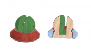
I decided on a stackable gearbox design, which consists of repeats of the same section, each one accounting for a 11/17 reduction in final drive ratio, resulting in a 5.7:1 ratio at the output.
This leaves room for a further reduction at rear axle (13/21, for example, would result in a final drive of 9.2:1)
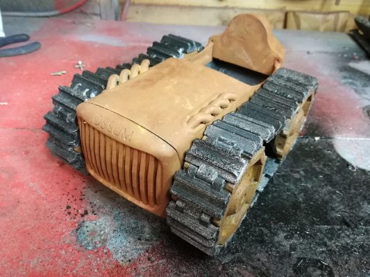
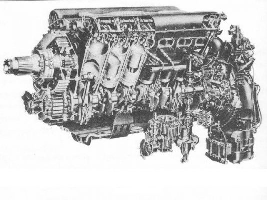
Engine Model
Just because we are forced to use an electric motor doesn’t mean we have to look at one, so I began the design of a Merlin V12, scaled to 1:10. This engine will go over the electric motor, and given it’s size, probably also hide some electronics or the steering servo.
There are of course many details to go, but having the rough shape helps me work out the car’s final dimensions.
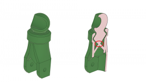
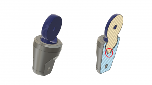
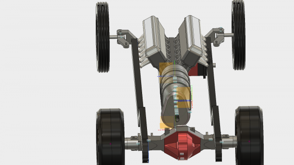
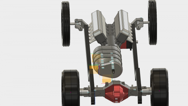
Gearbox Location
The gearbox can be orientated horizontally or vertically, which I am not yet decided on. I prefer the vertical orientation for aesthetic reasons, but horizontal may be more practical.
Either way, the motor stays at the lowest point, and the output is roughly in line with the rear axle input shaft.
Up Next
The next most pressing issue is probably to design the rear axle, and the telescoping driveshaft that will connect it to the gearbox, so stay tuned. In the meantime, I am curious to hear your thoughts!


